




"Design a House with AutoCad Architecture 2018"
Published - Copyright© 2019 by Pantelis Skourtis
At this step, you will draw the architectural plans of the project house21-190, the floor plan of the basement, the plan of the ground floor, the plan of the first floor and the floor plan of the roof - attic. Then you will draw the 2D site plan and the 3D Terrain drawing.
These plans can then be used, with the usual procedure of Autocad Architecture, to create the rest of the architectural drawings such as sections, elevations, 3d Views etc.
The ACA (AutoCad Architecture) software provides special tools to organize your projects so that you can create drawings and project information in the quickest and easiest way. You will apply this procedure during the designing of this project as described in step "4. Drawing Management".
The floor plans and site plans that you will draw in this phase, will be used later in stepr '5' to create the Construct Drawings which form the core of the work drawings.
- Details
{jcomments on}
"Design a House with AutoCad Architecture 2018"
Published - Copyright© 2019 by Pantelis Skourtis
2.4.1- Create the Roof and Attic Outline
A portion of the roof, the part (BmgD1B) consists the attic space, created under the roof (kmghk) of the house (Fig.2.4.1.1).
You will use the outline (kmghk) of the h21190_firstFloor_outline.dwg, that you created in previous chapter, as the firstfloor outline.
You will draw polyline (abcdefgha) that is the ground floor outline, polyline (kmghk) that is first floor outline, and for this drawing will be the roof outline, and polyline (BmgD1B) that is the attic outline, according the dimensions and position you see in Fig.2.4.1.1.
Be careful, to set all these polylines at level 0.00, and that the X, Y coordinates of point (h) are 00.00, 00.00, similar to those in the first floor plan.
You can download the drawing of this polyline (kmghk) by clicking here: dwg for Fig. 2.4.1.1. On the website you will be directed, locate the file roof_outline.zip on category Custom Drawings/ Roof, click on this file name to download it, then unzip and save it in the folder: C:\ACA\My_projects\house21_190\downloads\roofAttic\, under the name roofAttic_outline.dwg.
Using as guide the roof outline, you will draw at the next chapter the hipped roof and the exterior walls, with thickness of 0.30 (m) and height 0.60 (m), onto which you step the roof.

Apply Hatch
Hatch fills an enclosed area or selected objects with a hatch pattern, solid fill, or gradient fill.
To draw hatch within the areas (bmgD1), as shown in Fig.2.4.1.1:
- On Ribbon, create a new layer, with Name: A-Pattern, Color: 41, and make it current.
- Click Home tab ►on panel Draw ► select Hatch icon
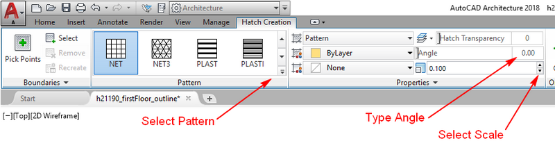
 , the Hatch Creation ribbon will appear (Fig.2.4.1.2)
 - On panel Pattern, click on the arrow to open the drop-down window with the available patterns, and select the pattern NET.
- On panel Properties, for Angle type 45, and for scale set 0.1.
- At the prompt: HATCH pick internal point or [ ]: Pick a point within area (bmgD1), and then press Enter.
- The result is as shown in Fig.2.4.1.1.
- You have created in advance the folder: house21_190/customDwg to cluster the plans you will create at this stage of the design (floor plans and site plan).
The full path of this folder is: C:\ACA\myProjects\house21_190\customDwg.
In this folder create four sub folders with names: basement, groundFloor, firstFloor, roofAttic, and sitePlan, where you will save the relevant drawings that you are going to create in this phase of the project. -

Fig.2.3.2.8 - House21-190 - The Dwg folders
Press Esc and save your drawing under the name: h21190_roofAttic_outline
in the folder: C:/ACA/myProjects/house21_190/customDwg/roofAttic