




"Design a House with AutoCad Architecture 2018"
Published - Copyright© 2019 by Pantelis Skourtis
In this step, you will create for the project House 21-190 the plans of the first floor, and you will save theese in a folder under the name firstFloor.
The steps to follow are:
- 2.3.1 - Create the first floor outline
2.3.2 - Design the exterior walls
2.3.3 - Design the interior walls
2.3.4 - Place the doors - 2.3.5 - Place the windows
2.3.6 - Create the roof slabs
2.3.7 - Create the interior stair
2.3.8 - Open a hole in the Slab
Within folder C:\\ACA\myProjects\house21_190\customDwg make sure you created a folder called firstFloor. If you have not already done so, you can do it now.
You will use it to store the drawings you will create for the first floor in this phase of designing.
You can also download these drawings from the web site by clicking here: download-dwg-h21190. Save these drawings in the folder downloads, and use them during designing.
The full path of these folders will be respectively: C:\ACA\my_projects\house21_155\customDrawings\firstFloor\ and C:\ACA\myProjects\house21_190\customDrawings\downloads\.
- Details
"Design a House with AutoCad Architecture 2018"
Published - Copyright© 2019 by Pantelis Skourtis
2.3.4 - Place the Doors of First floor
The next step is to design the doors of the first floor. The doors are placed in the project as objects with three dimensional attributes.
After these mounted on a wall, the wall will be automatically cut and processed, and the doors or windows remain anchored on the wall.
These are held on the wall and can’t be moved away. When the wall is moved or resized, the position of the door or window on the wall remains stable. To delete a door, select it and click Delete.
Open with AutoCAD Architecture the drawing, you created in the previous lesson, under the name h21190_firstFloorWalls, or if you wish you can download it by clicking here. Unzip and open it, with AutoCAD Architecture.
You will continue working on the First floor drawing adding the necessary doors in the plan of the first floor you've created so far.
You will place two exterior doors leading to terraces, and three interior doors, with the location and the dimensions shown in the sketch 'First floor - Doors' (Fig. 2.3.4.1).

Placing the Doors
You can select the Door tool from Ribbon > Home tab > Build panel > Door fly out menu (hover on ►) >select Door , or you can select it from Tool palette - Design (Fig. 2.3.4.2).
- The doors selected from the tool palette-design (design Tool palette) or from the Table Build of the Home tab have the standard style.
You can use for doors and windows another style different of the 'Standard' style.
To do this: - In the Tool Palettes - Design click the Doors tab (Fig.2.3.4.2), to make the tool palette Doors active (Fig. 2.3.4.3).
- In the opened Tool Palette 'Doors' (Fig. 2.3.4.3), you will see the door styles that are available for use, and you can choose the style of door you prefer.
-
Fig.2.3.4.2 - Tool Palette - Design 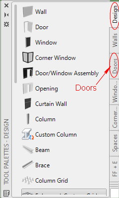
-
Fig.2.3.4.3 - Tool Palette - Doors 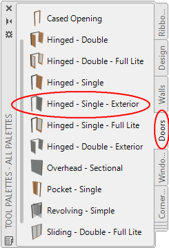
When you select a door tool, the properties palette (Fig.2.3.4.4) of the selected style door will open. In the fields of the Properties palette you can see its properties, such as style, height, width, head height and other that you can edit.
- For the two doors on the walls (B1M) and (MG) of your plan, select on the 'Door tool palette' (Fig. 2.3.4.3) the Hinged - Single - Exterior door style.
On the Properties palette which will appear (Fig.2.3.4.4), you will see the properties of the door style you have chosen. - In the Properties palette edit the properties as follows: In category Dimensions, type the following: Width = 0.90, Height = 2.10, Measure to = Outside of frame, Swing angle = 90.
- In Category Location select position = Unconstrained.
This choice allows you to set the position of the door by entering values using the dynamic dimensions (Fig.2.3.4.5) or to determine their position with the mouse.
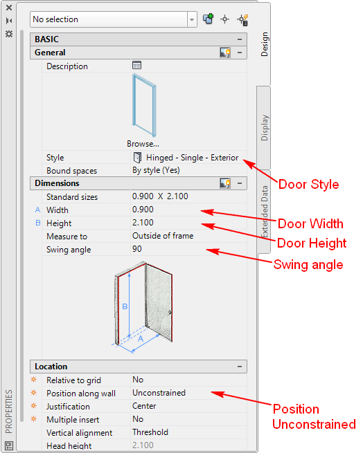
- After selecting the door style Hinged - Single - Exterior, appears the prompt: Select Wall, grid assembly or Enter: select the wall (B1M) close to point (B1).
After selecting the wall, the dimensions are displayed dynamically indicating the position of the door (Fig.2.3.4.5).
To make appear the Dynamic dimensions tool, the selection Dynamic Input on 'Application status bar'
  has to be ON (it's color has to be cyan).
Move the cursor from left to right or from right to left, to adjust the swing (swing) door.
Move the cursor up and down from the wall to determine the location of the door along the wall you have chosen.
The hinge point of the door can be changed using Handle points (grips)(Fig.2.3.4.6).
The dynamic dimensions, as shown in Fig. 2.3.4.5, indicate the distances of the door from the edges of the selected wall. The active dynamic dimension is indicated by a blue background.
Press the TAB key to switch the activation of each 'dynamic dimension' box. The activated dimension box is colored blue.
- At the prompt on dynamic dimension: Insert point or:
Press Tab to activated the right box of dynamic dimension (the background is blue) and entered 1.65, which is the distance of the door you entered from the right edge of the wall [B1M], is the distance from point [M], (Fig2.3.4.1), press ENTER to accept the value and press Esc or Enter, again to complete the command.
You will now create, in the same way, the other one door on wall (MG) using the same door style Hinged - Single - Exterior. Then you will create three doors with style Hinged - Single and same dimensions, two of which on wall (B1D), will have as width 0.90, and one on wall (HG) with width 0.80, as shown in Fig. 2.3.4.1 "First floor - doors."
Selecting the door you mounted on wall (B1M (Fig. 2.3.4.5), you will notice the handles - grips (Fig. 2.3.4.6).
You can use the handles to move the door along the wall, change the position of the axis of rotation and change the width of the door.
You canto change the position of the axis of rotation for door (the position of hinges), or to flip it from the left to the right side.
In order to do this, with the door still selected, press the handle which activates the Flip (hinge) as shown in Fig.2.3.4.6, and the door will swing to the other side of the wall.
Using the mouse and grip points (Flip grips) of a door (Fig.2.3.4.6), you can flip the direction and position of the hinges, to be as shown in the 'Basement - doors' in Fig.2.3.4.1.
-
Fig.2.3.4.5 - Place the Door 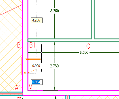
-
Fig.2.3.4.6 - Flip (Hinges) Door 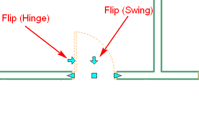
Having selected the door, the Properties Palette will appear. You will then see the properties of the door you have choose and which has the Style Hinged-Single - Exterior.
• In the Properties palette notice that the properties of the selected door is the following:
In category Dimensions, Width = 0.90, Height = 2.10, Measure to = Outside of frame, Swing angle = 90,
After Installing the doors in the plan of the first floor, the result will be as shown in sketch basement - Door to Fig. 2.3.4.8.
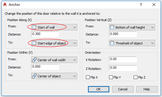
You can move the door position using your mouse. For more accuracy you can use the 'Anchor' of the door properties.
Select the Door ► properties ► on category Location ► select Anchor to open the Anchor panel settings (Fig.2.3.4.7).
Using these Anchor panel settings, you can change the position of selected door relative the wall it is anchored to. For the door on wall (B1M), on Anchor dialog box, and on category 'Position Along (X)', for 'From' select Start of wall, (it is the exterior wall (km)), for 'To' select Start Edge of Object and for 'Distance' type 1.95 (it is the sum 1.65 + 0.30) as shown in Fig 3.2.4.1.
The plan of the First floor, after the design of the doors, will be as shown in Fig.2.3.4.5.
Save this drawing under the name h21190_firstFloorDoors in the folder customDwg\basement you have created.
The full path will be: C:\ACA\myProjects\house21_155\customDwg\firstFloor\h21190_firstFloorDoors.
3D Isometric View
To have a 3D isometric view of your project, on the View Cube tool, at the upper right corner of your screen, click on the corner WS of the Cube.
You can apply a Conceptual style view in your drawing to have a more artistic view:
- To set the Visual Style of the drawing, on Ribbon > click on View tab > click the arrow on Visual panel (hover on ►)
 , the drop-down which will open provides a choice of visual styles defined in drawing to make current (for the moment the current visual style is the 2D Wireframe) > select Conceptual, to make this visual style current.
The result is shown in Figure 2.3.4.9.

At the next lesson 2.3.5 - First floor - Create the Slabs, you will create the slabs for First floor.