

"Design a House with AutoCad Architecture 2021"
Published - Copyright© 2021 by Pantelis Skourtis
In this step, you will create for the project House 21-260 the floor plan of the basement under the name h21260_basement.
In the procedure to design the basement you will draw the following:
- 2.1.1 - Basement h21260 - Outline
2.1.2 - Basement h21260 - Exterior walls
2.1.3 - Basement h21260 - Interior walls
2.1.4 - Basement h21260 - Doors - 2.1.4a - Basement h21260 - Windows
2.1.5 - Basement h21260 - Create theSlabs
2.1.6 - Basement h21260 - Create theStair
2.1.6a - Basement h21260 - Open a hole on Slab
- Details

2.1.6- Create the interior stair up to the ground floor
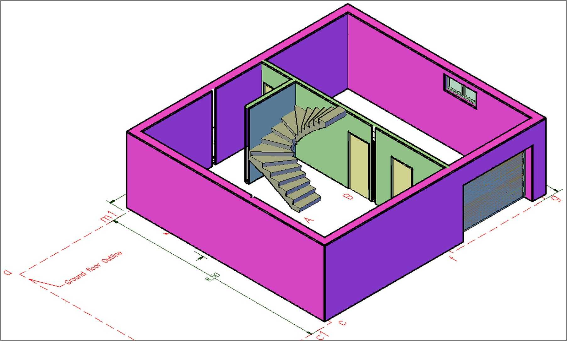
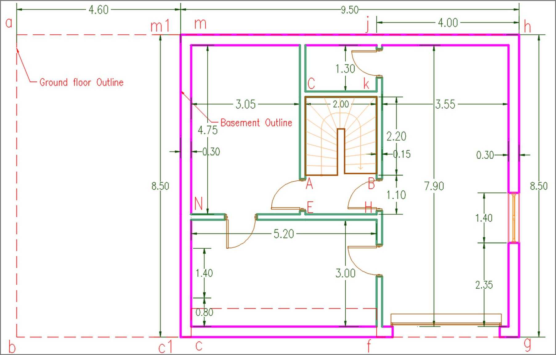
In this step you will create the interior stair of the basement; this is a Multi–landing, ½ turn stair starting from the basement, on the top of the floor slab, (elevation = 0.20), and leading up to the ground floor, as shown in Fig.2.1.6.6, and 2.1.6.8.
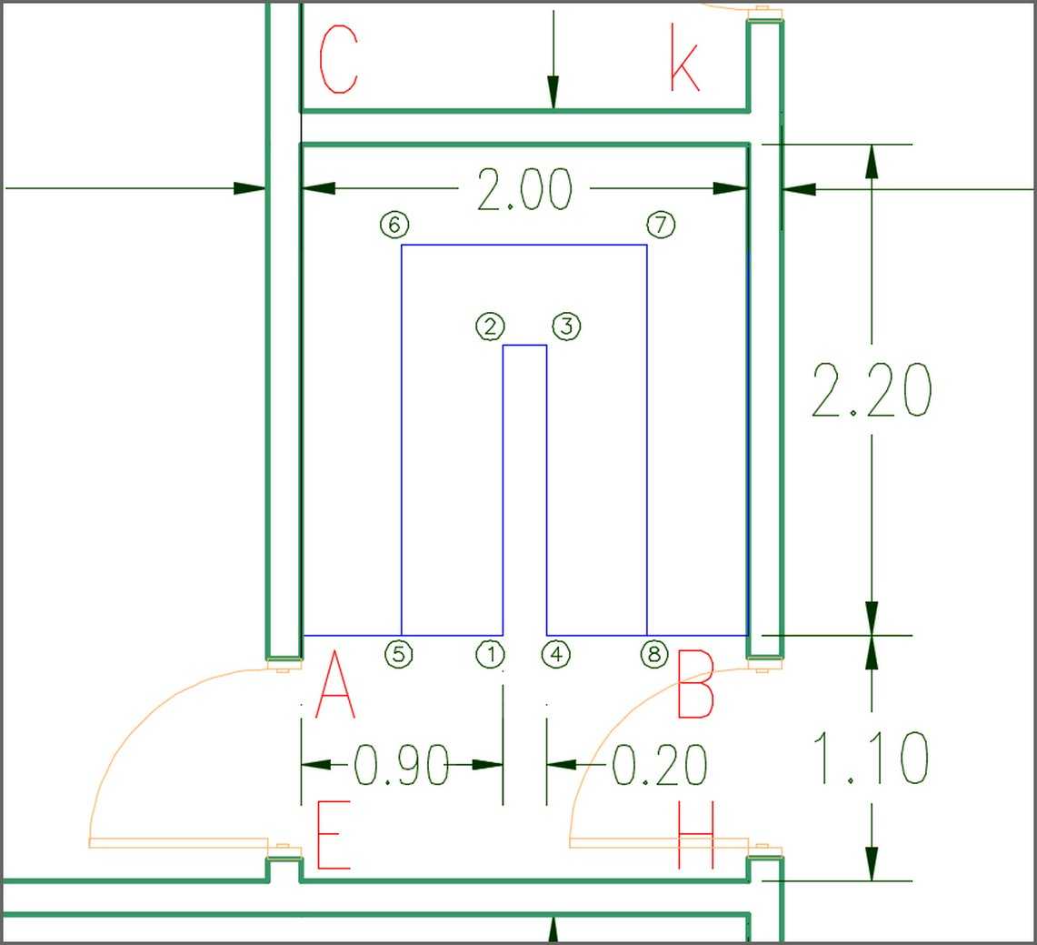
The position of the stair on the basement floor plan as well as its dimensions are as shown in Fig. 2.1.6.5 and 2.1.6.6.
This stair is a Multi-landing stair. To design it you will use from the Design Tool Palette (Fig. 2.1.6.1), the type of stair called Concrete.
If there is not this type of stair in 'Design Tool Palettes', you will get it from the Content Browser to add it in Design Tool Palettes.
• To do this: Open the Content Browser:
• On Ribbon > Home tab > click on Tools > and select Content Browser (Fig. 2.1.6.2).
• On the Content Browser which will open, select > Design Tool Catalog > Stairs and Railing > Stairs (Fig. 2.1.6.3) > select the Concrete Stair and select > Add to Tool Palette.
-
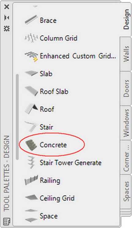
Fig.2.1.6.1 - Tool Palette - Stair -
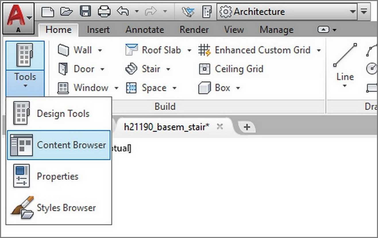
Fig.2.1.6.2 - Open Content Browser
On the floor plan of the basement, draw the polyline (A C k B (4) (3) (2) (1) A), according to the dimensions shown in Fig.2.1.6.5, it is the footprint of the stair as it is to be fitted.
You will design the stair using the stair style "Concrete" that you'll get from the Design Tool Palettes or the Content Browser.
The stair will be designed with the qualities of the type of stair you choose on the design tool palette, and in accordance with the treatment, you will do on its properties.
You can edit anytime the properties of the stair in the Properties Palette (Fig.2.1.6. 4).
-
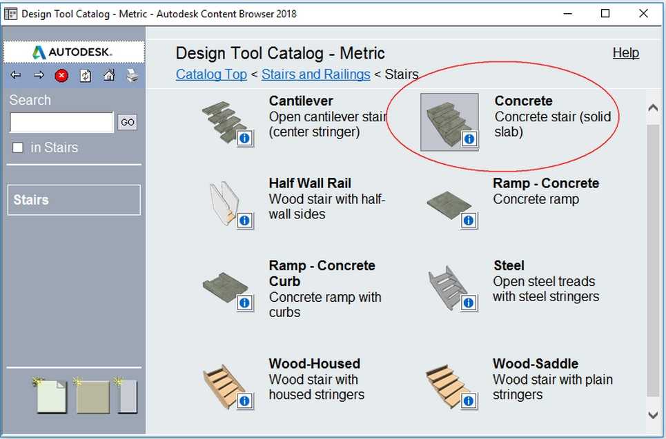
Fig.2.1.6.3 - Content Browser - Concrete Stair -
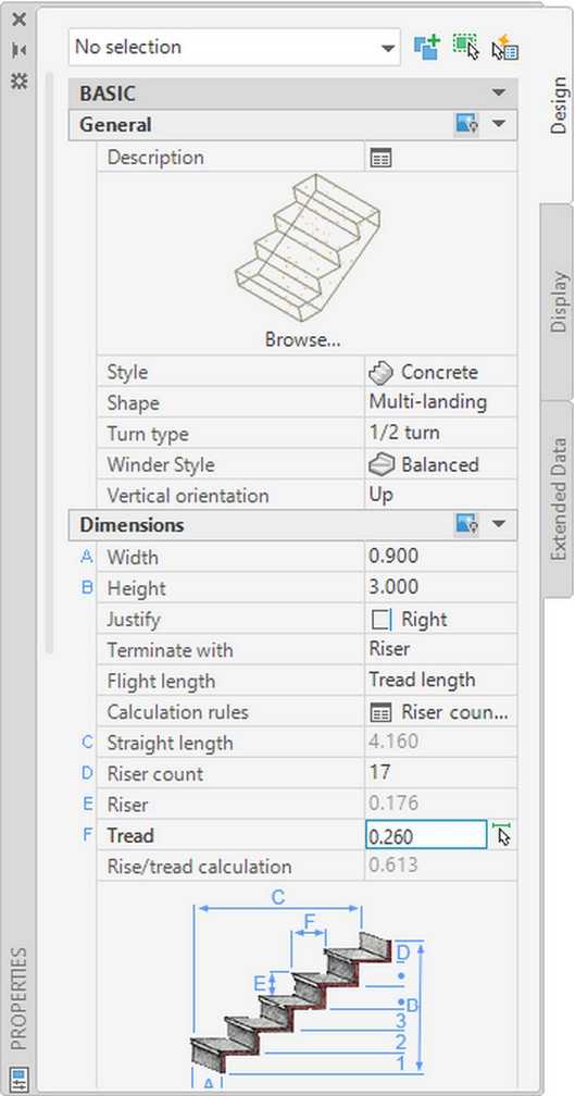
Fig.2.1.6.4 - Properties - Stair
Design the stair.
- Open the Design Tool Palette, right-click on the stair style Concrete (Fig. 2.1.6.1), the Properties Palette of this stair will open (Fig. 2.1.6.4), where you can modify the values according to your needs.
Alternatively, you can select the Stair tool on Ribbon:
You click on Home tab > Build panel > Stair drop-down > Stair. - On the Properties Palette (Fig. 2.1.6.4), select Multi-landing for Shape, ½ turn for Turn type, Right for Justify, and select Riser for the 'Terminate with'.
- Define the value of Width to 0.900 (A (1)) = 0.900 m), of Height to 3.000, of Tread to 0.260, and the Riser Count to 17.
- On category Advanced > Interference define the Headroom height to 2.800, and the Right clearance to 0.200.
• At the prompt First Star Point: select point (1). - At the prompt Flight End Point: select point (2).
- At the prompt Flight End Point: select point (3).
- At the prompt Flight End Point: select point (4), and press ENTER.
The stair has been created as shown in Fig. 2.1.6.6.
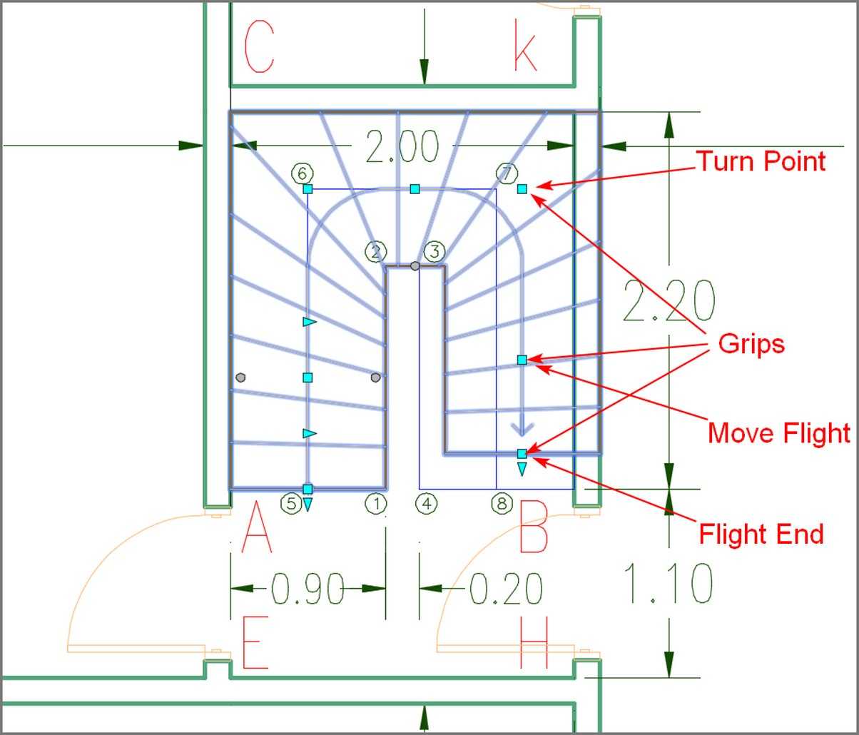
If the stair doesn’t fit with its footprint, you can move it to the exact position using the grips.
Clicking on the stair you will notice the grips (Fig.2.1.6.7).
Select and move with your mouse the grip “Turn Point” to point (7), and move the grip “Flight End” perpendicular to line ((7) (8)).
The stair will be placed in its final position, as shown in Fig.2.1.6.6.
Create a 3d Conceptual view
To create a conceptual 3D isometric view:
- Click on the corner WS of View Cube icon
 to get a 3D isometric view of your project or select the 'Top' from the View Cube to get a floor plan of your project.
 - • You can apply a Conceptual view of your plan to have a more artistic view (Fig.2.1.6.8).
To do this:
• On Ribbon > click on View tab > select Visual panel > select Conceptual
• To have a better three-dimensional picture of the stair, you can hide some of the walls, that hide the stair.
To do this:
• Select the walls you want to hide - in this example, you will hide the walls (CE), (NH) and their openings- click Isolate Objects icon  , (the icon in the status bar, at the bottom - right corner of your screen), and choose to Hide Objects.
The walls (CE), (NH), and their openings will be hidden and your drawing will be as shown in Fig. 2.1.6.8.
• To make the wall reappear, right-click on the screen that displays your design, and in the window that opens select: Isolate Objects > End Object Isolation.